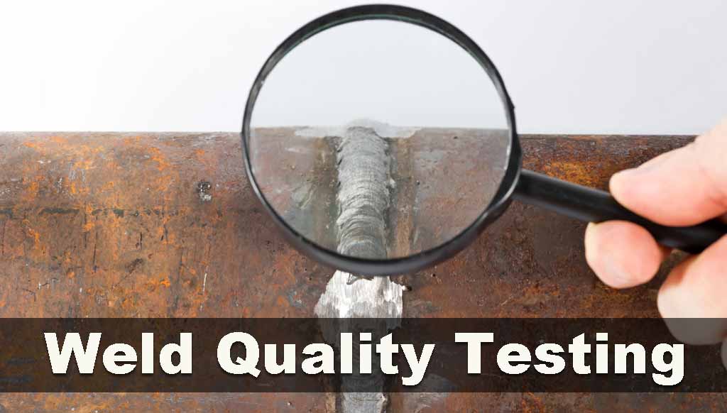
Quality Weld Inspection – Nondestructive Testing
On completion of welding, the satisfactory performance of the welded structure can be determined by the testing procedures. The proof tested procedures to test under conditions similar to more severe than those that happened by the welded structures in the field. We aim to discuss the quality weld testing here to judge the welded structure in the utilities.
Here we are going to discuss the visual inspection tips for GMAW and physical testing of the welded part. These quality weld tests can detect the weak and defective material that can be amended before it is released for use in the field. These weld tests help to design welding and types of equipment, forestall injury, and difficulties to the welders.
Nondestructive testing or NDT is an approach to testing that involves evaluation without causing any damage to welded material. The NDT is the method that includes visual weld inspection, x-rays, ultrasonic testing, and liquid penetration tests. These tests save time and money.
In the majority of welds, the quality can be assessed for the function for which the weld part is intended. You fix a welded part on a machine, and the equipment functions smoothly, then the weld is considered as a correct one. There are manners to judge if a weld is flawless.
1. Distribution of Weld Material –
The equal distribution of the weld material between the two materials that was fastened.
2. Free of Waste –
The weld is without any waste material such as slag. The slag can be peeled off on the cooling of the project easily. MIG welding residue from shielding gas can be removed easily. TIG welding is known as clean welding and if waste is seen there, it means the welded material was not properly cleaned.
3. Porosity/Porous Holes –
We need the weld surface, regular, smooth, and without any porous holes. These porous holes lead to weakness of the structure which indicates that the base metal was not cleaned properly or is having an oxide coating. In the case of the MIG or TIG welding process, this porosity is an indication of improper shielding utilization as this improper use may lead to porosity.
4. Tight Joint –
Loose joint always indicates the weld problem. In oxyacetylene and TIG autogenous welding where filler material is not used, the weld must be tight. The gap is not very troublesome in other types of welding as the gap is filled with filler material. The gap otherwise is a quality issue and weak weld.
5. Leakproof Weld –
When repairing an article containing liquid, a leak in the vessel is an obvious way to detect the problem. F or the vessel that contains gas, the testing is done by putting soap bubbles over the vessels to detect the leak as in a squirt bottle.
6. Weld Strength –
This is required in most situations. The easy way to ensure the strength is to choose a filler metal and electrode the rating of those higher than your needed strength.
The other visual weld inspection methods include before the weld as root face, angle of the bevel, gap, joint fit. During the weld electrode consumption rate, the flow of metal, arc sound, arc light. After the weld undercut, pinholes, root fusion issue, excessive spatter, dimensions of the weld. We will be discussing these in the following pages.
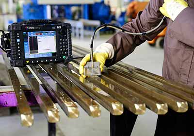
Ultrasonic Testing
Common Welding Defects
1. Incomplete Penetration
The incomplete penetration happens when filler matter and base metal do not fuse together at the root of the weld joint. The completion of the groove welding with deposited material and base metal had not joined completely at the root of the desired joint. The commonest cause of this incomplete penetration is unsuitable weld design not suitable for the welding process. When we weld the groove from one side only, incomplete penetration is the possibility due to the following conditions.
The dimension of the root face is too big although the root opening is of adequate size.
- Too small root opening may be the cause
- The angle in a V-groove included is too small
- Larger size electrode
- Very high travel rate
- Too low welding current may be the reason
2. Lack of Joining and Fusion
The failure of the welding process is due to a lack of joining and fusion between layers of weld and base metal. The weld metal rolls over plate surfaces and termed as overlap. The lack of joining and fusion is caused by the following conditions.
- The base metal and deposited metal fail to rise to the melting point.
- When fluxing is improper and fail to dissolve the oxide and other foreign material to the metal to be fused.
- Dust and dirty plate surfaces.
- The type and size of the electrode are inappropriate.
- Bad adjustment of current.
3. Undercutting of Base Metal
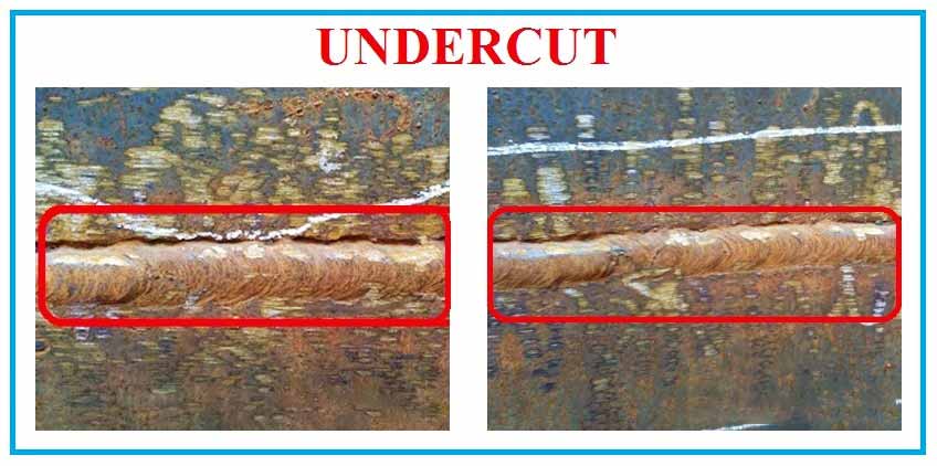
The burning away of the base metal is called undercutting. The causative reasons are following
- Too high current adjustment
- Too long arc gap
- Crater filling is failed with weld metal
4. The Slag Inclusion
The globular and elongated pockets of metal oxide and other compounds are termed slag inclusions. They result in the porosity of the weld metal. In arc welding, slag inclusions consisted of electrode coatings, fluxes, and other materials. Failure to remove the slag in multi-layer welding leads to slag inclusions. This slag inclusion can be prevented by the following:
- Always prepare the groove and weld material properly before each bead is placed.
- Remove all the slag.
- The slag should rise above the weld pool to remove it.
- Never leave any contour which is difficult to penetrate fully with the arc welding.
5. Porosity
Porosity is defined as pockets that do not have any solid material. The difference between a slag is that it contains gas rather than s a solid. The gas here derived from:
- Gas released from the cooling of the welding as it reduces solubility temperature falls.
- Gas as a by-product of chemical reaction in the weld.
Porosity can be avoided and prevented by:
- Undercutting and overheating of the weld metal.
- The current setting is too high.
- Arc is too long.
Visual Weld Testing and Inspection
An open eye inspection or visual welding inspection is a non-destructive testing (NDT) where weld quality is judged with the help of the eyes for surface discontinuities. This is the most common method to judge the weld quality.
Advantages of NDT (Nondestructive) for weld quality
- Inexpensive at labor expense only.
- Low budget equipment.
- No need for power.
- Quick detection of welding defects helps to reduce the cost of repairs if not detected early.
Disadvantages of NDT for welding
- Good eyesight is necessary.
- Training by an inspector is needed.
- Possibility of missing internal defects.
- Only the inspector can record the defect and record them.
- Human error is a possibility.
Steps for Visual Weld Quality Testing
- Practice and establish procedures for a consistent approach in an application.
- inspect the weld material just at the beginning of the process.
- Watching the quality once welding the material.
- Complete inspection at the finishing line.
- Mark every problem in the weld and remove and repair the weld.
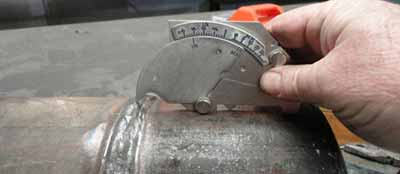
Visual Weld Quality Test Equipment
The visual weld quality testing requires several small or big types of equipment.
1. Weld fillet gauge handheld to measures.
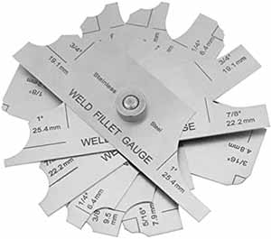
- The flat weld
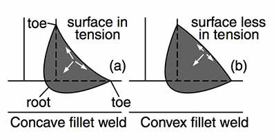
- Convex or rounded outward weld
- Concave or rounded inward
2. Protective glasses with the pocket viewer and shaded lens to observe the welding process.
3. The magnifying glasses as per the requirement.
4. The flashlight
5. Hammer and chisel to remove the slag to inspect the weld clearly.
6. Temperature equipment pyrometer, tempelstick to measure preheating, inter, and post-heating.
7. Magnet to determine the type of metal
8. Measuring tape
9. Calipers
Visual Weld Inspection
- Examine the drawings carefully.
- Find out the weld position and how it relates to the specifications. Keep a watchful eye on the vertical direction of the weld.
- Look into fillet welding symbols.
- The procedure should align with codes and welding specifications.
Weld Material Inspection
The following steps to be ensured for weld quality testing for assembly inspection:
- Scan for fit.
- Check the alignment of fixtures and jigs for any spatter of the previous job and clean them completely.
- In the case of tack weld, check the quality as there should be the same electrode as in the main welding.
- Examine the use of preheating as it slows down the cooling speed and results in minimum distortion.
Weld Equipment Inspection
- Scan the damage in cables, electrode holder, and grounding clamps.
- Scan the voltage of the arc.
- Scan the ampere meter for the range of our work specifications.
Visual Welding Inspection during the Weld
- Examine the size of the electrode, type, and storage as the low carbon electrode needs a stabilizing oven.
- Check the root pass to judge susceptibility to crack.
- Scan every weld pass and look for undercut and required shapes. Make a point to clean the weld properly between each pass.
- Watch the craters those need to be filled.
- Probe weld sequence & size judged by the gauges.
Visual Welding Inspection after the Weld
- Scan the weld for the code and standard followed.
- Scan the size with gauges and prints.
- Probe the finishing of the weld and its contour.
- Examine the cracks for the standards.
- Keep a watch on the overlap.
- Be watchful for the undercut.
- Probe for the acceptable standard of spatters.
Visual Weld Testing of Gas Weld
The weld quality of the gas weld by inspection has the following criteria:
- The consistent width of the weld needs to be maintained. Two edges of the weld should be in straight parallel lines.
- The face of the weld ought to be slightly convex with the addition of approx.1.6mm above the base metal surface. This convexity should be regularly even throughout the length and not high or low at some places.
- The face of the weld has ripples that are fine and evenly spaced, There should not be excessive scales, spatters, and pits.
- No, undercut or overlap at the edges of the weld.
- There should be a complete blend of starts and stops beyond any recognition.
- The craters at the end of the weld should be filled completely without a sign of any hole, crack, and pit.
Weld Testing of Butt Joint
In the case of the butt joint, examine the backside of the weld to judge the complete penetration passing through the root of the joint. A tiny bead should form on the backside to judge the complete penetration through the root of the butt joints.
Lap and T Joint Weld Testing
The fusion and root penetration of these laps and T-joints can be assessed by exerting pressure on the upper plate until it bent to double. If the penetration is not completely through the root, then the plate will crack open at the joint on bending. In the situation of the break-in plate, judge the extent of the fusion and penetration as it lacks complete penetration and fusion.
Final Words
A successful weld quality control system needs its induction and the complete control of this inspection program. To establish a program needs a complete evaluation of the weld quality requirement, its acceptance, knowledge of inspection, and details of the welding methods, and introduction of a qualified and experienced welding inspector.
Develop a system to evaluate quality with specified acceptance criteria and the person with knowledge and experience to establish the quality. Spare a few moments to pen your comments and thoughts here.
Related Posts