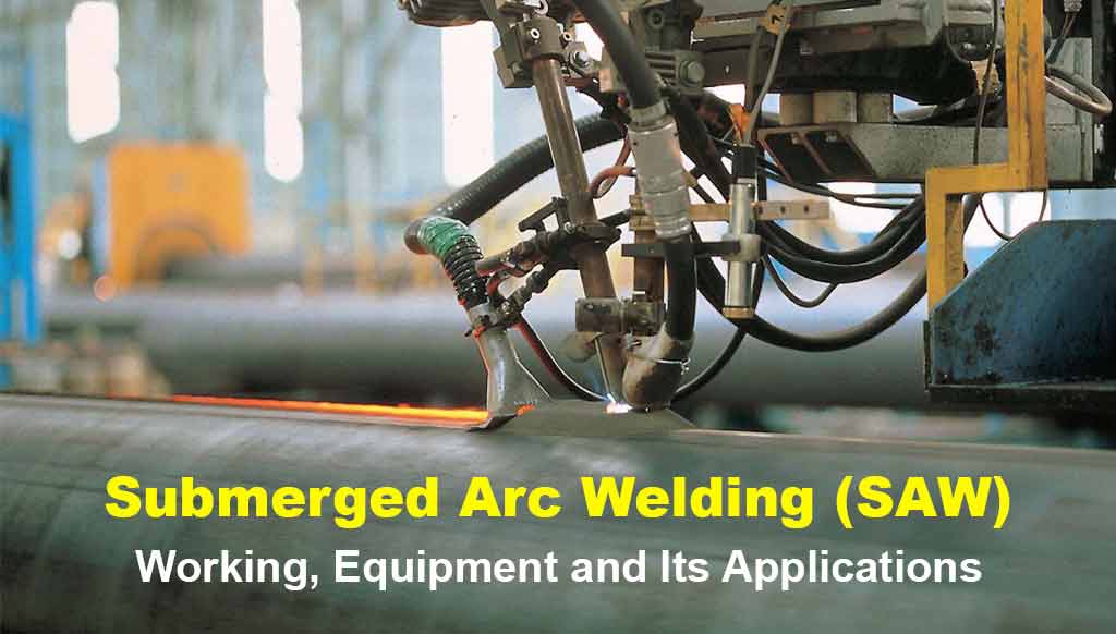
Submerged Arc Welding (SAW): Working Process, Equipment, Parts, and Its Applications
Submerged arc welding (SAW) is a welding process where the tubular electrode is fed continuously to join two metals by generating heat between electrode and metal.
The area of the arc and molten zone gets its protection from the atmospheric contamination by submerging under a blanket of granular flux. The flux layer covers the area completely preventing spatter, sparks, fumes, and UV radiation.
Higher deposition rates than other Welding processes.
Operator friendly – no visible arc, no spatter.
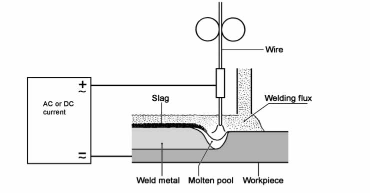
Principle of Submerged Arc Welding
Are you looking for:
- Increased production
- Increased welding speeds
- Increased deposition rates
👇 This is a solution.
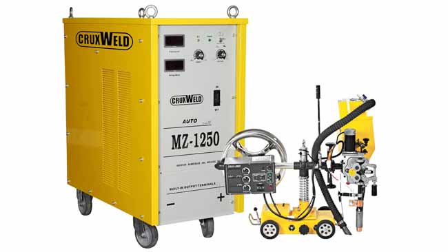
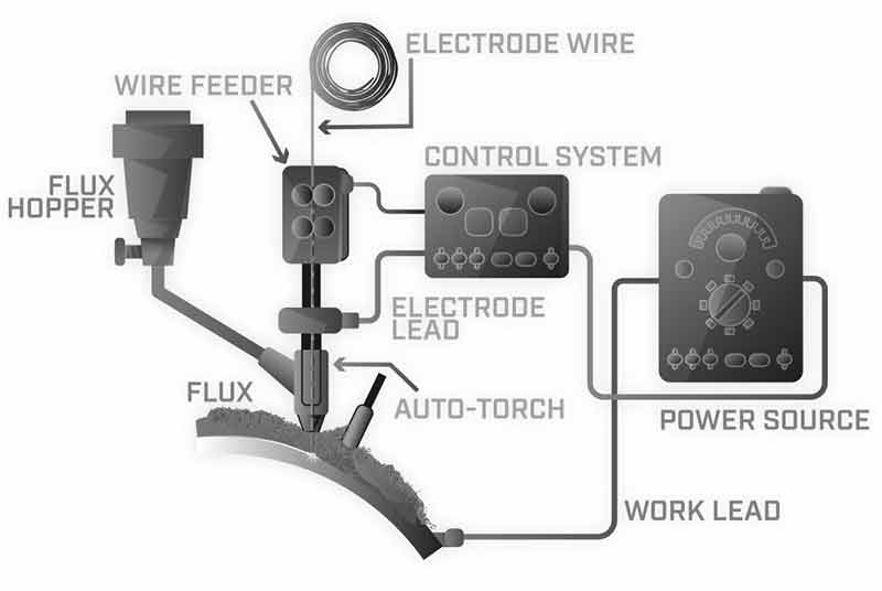
SAW Equipment
Arc formation between the wire electrode and workpiece happens as in the MIG welding process. But this process has an additional advantage of shielding by the granular flux making the SAW welding as spatter, fumes, and UV light free. The equipment has the following in its inventory.
Submerged arc welding can be used with DC or AC.
- Power source
- Welding torch/gun and cable assembly
- Flux hopper and its feeding
- Travel mechanism for automatic welding
SAW Welding Working
1. Power Source
We need a power source for this submerged arc welding at a 100% duty cycle. The SAW welding process is continuous and the length of one weld may go up to 10 minutes. General power sources with a 60% duty cycle may get derated according to the duty cycle curve of 100%. The voltage sensing wire feeder must be used when a constant current of ac/dc applies. The fixed speed wire feeder uses a constant voltage while the CV system drives with direct current.
Both the process DC generator and AC transformer may be used but rectifier machines are more popular. The submerged arc welding machine available in the range from 300 amperes to 1500 amperes.
The direct current equipment suits semi-automatic applications while alternating current power source fit for the automation only. The extra power can be achieved by joining both in parallel. With AC type equipment, the use of multiple electrodes is possible in specialized types of applications.
2. Welding Gun and Cable Feeder Assembly
This part of the equipment needs to carry the electrode and even flux to the site of the arc. A small hopper for the flux is attached to the end of the cable assembly. The bottom of the hopper has an outlet for the electrode wire through a current pickup terminal of the arc.
The gravity comes into action for the flux feeding. The amount of flux to feed depends upon the height of the gun held above the working station.
3. Flux Hopper
The hopper gun has a soft switch to start the weld. It may use hot electrodes as when it touches the workpiece the feeding starts automatically. In the automatic process, it attaches the torch to wire feed motors and the current pickup tip for the welding process. This hopper is normally attached to the torch which has a magnetically operated valve, open and closed by a control system.
4. Travel Mechanism
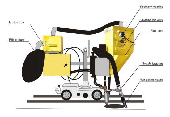
The process of welding is customized at a very fast pace using the travel carriage. This may be available in tractor-like structures. The flux recovery unit normally collects the unused flux and returns it to the hopper for supply. The general movement of the tractor is in a horizontal direction.
SAW Welding Diagram
Merits of SAW
The major merits hold by SAW/Submerged Arc Welding Process includes.
- Great speed, best deposition rate at a faster pace.
- Superior welding quality.
- Hardly any smoke
- Smooth, finely finished, and uniform welding with no spatter
- Safe to the welder, no spatter, no arc flash
- Automation is easy here.
- Excellent utilization of electrodes.
- No manipulative skills
- Minimal metal distortion
- Can operate the machine in windy areas
- No edge preparation of the material under 12 mm thickness
Major Applications
Fabrications – The process required in fabrications of pipes, penstocks, boilers, structural shapes, pressure vessels, railroads, rotary kilns, earthmovers, cranes, girders, bridges, locomotives, and under structures of railway coaches.
Automotive – Aviation, shipbuilding, and nuclear power industries.
The rebuilding of the worn-out parts and wear resistance alloy, tractor rollers, idlers, crane pulleys.
Suitable for metals like mild steel, medium, and high tensile alloys.
Limitations of SAW
- The welding process is not visible to the operator. He can not judge the quality or any defects. To overcome these shortcomings different jigs, fixtures, pointer, light beam, and roller guide may be added to judge and improve the result.
- Preplacing the flux over the joint to be welded, may not always be possible.
- It can weld only in a horizontal direction.
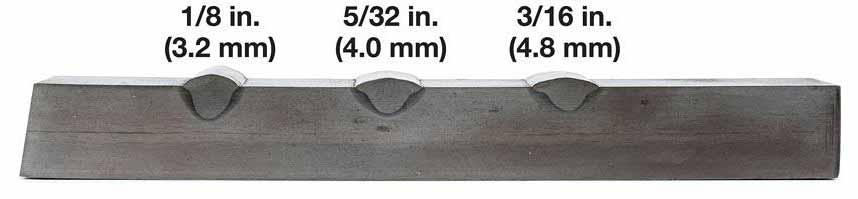
- The thickness of metal needs is 4.8mm, the lesser thickness will burn the metal.
- The edges of the metal to be welded should clean and fit accurately. The placing of flux will not be possible in irregular edges and may lead to the burning of the edges.
- The quality of the flux may be a cause of concern. Poor quality may lead to porosity.
- Cast iron, Aluminum alloy, Magnesium alloy, and Zinc alloy do not fit into the weldable material by SAW.
- The weld metal chemistry is tough to control as the flux alloys will change the characters completely of low alloys steel.
Process and Principle of Operation
In the submerged arc welding process the flux-covered electrode is replaced by the granular flux and a bare electrode. An arc between the electrode and job is the source of the heat and remains buried under a blanket of flux. This flux keeps the atmospheric contamination away. The process may be automatic or semi-automatic.
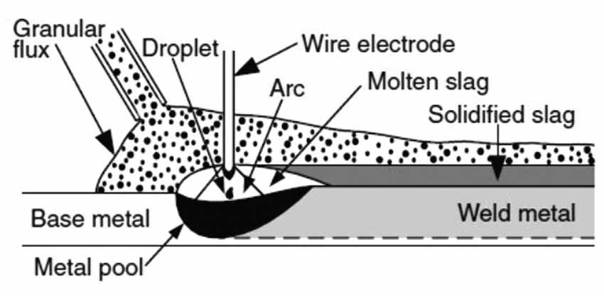
Once the trigger is pulled the flux starts depositing at the joint to be welded. The cold flux is a non-conductor of electricity, so arc may be struck by touching the electrode with the base metal. The arc may be struck by placing the steel wool between electrode and job metal and use high-frequency current.
It strikes the arc under the cover of the flux. once flux is heated and melt to become highly conductive. The upper layer remains unchanged and acts as protection while the lower layer remains electrically conductive to maintain the arc. The upper layer remains unchanged and granular, which can be reused.
The electrode moves a predetermined speed continuously to feed at the joint to be welded. The melted metal from the electrode is transferred to the workpiece and gets deposited. The flux close to the arc melts and intermingles with molten metals. This flux forms a slag lighter than the deposited metal as a protective layer. The weld remains submerged under a layer of flux and slag, so is the name submerged arc welding.
The electrode feeding is continuous by a coil. The arc is preserved automatically by flux. The travel may be managed by manual or by machine.
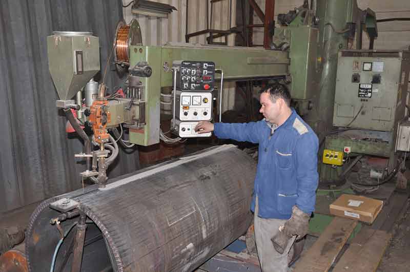
Application Method and Capabilities in Positions
The popular methods of SAW applications are Machine Method and Automatic Method. The machine method is the most common method where the operator keeps a watch on the welding operation. The automatic method is by push-button technique and the process applied semi-automatically but not a very popular method of SAW welding.
The process can not be sought manually as it is impossible to manage an invisible arc. The submerged arc welding process is a restricted position welding process. The restriction is because big molten pools and slag are fluid created which are difficult to hold in position. It suits the flat position best to them with a horizontal fillet position. We can weld at 3 o’clock under controlled situations.
The process is impossible to use in vertical or overhead positions because it cannot hold molten metal and flux in position.
Weldable Metals and its Range of Thickness
The process suits best to weld low-medium carbon steels, low alloy-high strength steels, tempered steels, quenched steel, and stainless steel. The submerged arc welding has tried experimentally on metals like nickel alloy, copper alloy, and uranium.
The thickness of 1.6-12.7 mm can be welded and there is no need to prepare their edges. The metal of 6.4-25.4 mm thickness requires edge preparation and can weld in a single pass. Thickness is practically unlimited with this procedure when the multiple-pass technique is used. The horizontal fillet can make up to 9.5 mm weld in a single pass.
Details of Joint Design
We can utilize the same joint design details as in stick welding. It shows the different joint details for the paramount utilization and productivity of the submerged arc welding. We can use the square groove design up to 16 mm thickness. The more thickness may require bevel designs. Open roots of weld design with backing bars are obligatory to hold the molten metals.
In the case of thicker metal on one side weld with a large root face, we may remove the backing bar. For better results with full penetration, the backing bar is required. The project with both surfaces accessible by backing weld can be made which will fuse to the original to offer complete penetration.
Welding Circuit & Current
The submerged arc welding process uses either direct or alternating current, but the direct current is used for most of the applications. Both direct current electrode positive (DCEP) and direct current electrode negative (DCEN) are used.
The constant voltage with the direct current power is popular for SAW with 3.2 mm and small diameter wire. The constant current system is used normally for welding 4 mm and bigger diameter electrodes. The control circuit for constant current is more complex as it tries to copy the actions of the welding machine to maintain a specific arc length.
The wire feeder needs to sense the voltage across the arc and sustain the electrode wire into the arc to maintain the voltage. The wire feed may slow or speed up to maintain the preset voltage across the arc. This will add complexity to the control system. The system does not react pronto. The striking of the arc is complicated as it needs use of the reversing system to start, retract, and maintain the preset arc.
The constant current power is invariably used with SAW welding. Multiple electrode wire is used with ac and dc arcs. We use here the constant power system. It applies the constant voltage when the two-electrode wire is fed into the arc supplied from a single welding power source. The welding current of the submerged arc welding can vary from 50 amperes to 2000 amperes. The commonest SAW welding is done within a range of 200-1200 amperes.
Welding Deposition Rates & Quality
The submerged arc welding has the highest rate of deposition compared to other arc welding processes. There are four reasons for more deposition in SAW welding.
- Polarity
- Long stick out
- Flux additives
- Additional electrode
The deposition rate is highest for direct current electrode negative (DCEN). The deposition in alternating current is in between DCEP and DCEN. The polarity with maximum heat contributes to the negative pole. The deposition rate with any welding increased with extending “stickout”. The point where current is to introduce into electrode and arc is the stickout. The longer the stickout poorer the penetration.
We can increase the deposition rate by adding metal additives in flux and using additional electrodes.
The weld metal deposited by submerged arc welding bars a beast quality. The strength and ductility of the weld metal exceed mild steel and low alloy material. This can happen when we use the correct combination of an electrode, flux, and the power source. The submerged arc welding used by a machine or automatic the inherent human error is removed and welding will be more uniform and free from defects.
The weld bead is much bigger with submerged arc welding compared to any other arc welding. The heat input is much higher so its cooling takes longer. The gases have enough time to escape. The slag here has a lower density and floats out to the top of the bead. The automatic process offers uniformity and consistency.
Troubles During SAW Welding
- The troubles are many but one is when electrode wire may be curved while leaving the nozzle and gun. The curvature in the wire will not deposit the location where it is intended to deposit. If you are welding in a deep groove, the deposition is there in the wall, not in the root leading to incomplete root fusion. It may trap the flux at the root of the welding.
- Maintaining the exact size of the weld and filling the weld groove blindly may not be an effortless task. We may overdo by placing extra weld or can underdo by making less deposit. The trained welder can overcome this trouble.
- The centerline cracking is the other issue. The extremely large single pass weld may entrap impurities and on solidification, it collects these leading on to centerline cracking. This is the possibility with a single-pass flat fillet with a 45-degree angle. Multiple passes can avoid it or change the angle by 10 degrees.
- The excessive hardness of the weld beyond 225 Brinell results from hard weld in carbon, rapid cooling, inadequate post welding treatment. Excessive alloy in the electrode may contribute to it.
- The defect may occur at the start and end which can be controlled by using a runout tab for start and stops rather than on the product.
Welding Variables
The welding variables are similar to the other arc welding processes, with several exceptions. We choose the electrode type and flux as per the metal to weld. The size of the electrode is directly proportional to the weld joint size and recommended current. The number of passes/ bead sizes to be considered and decide the joint. The same dimension weld can be done by multiple passes or few as the metallurgy suggests. Multiple passes deposit better and higher quality weld. Polarity decision is to be taken initially whether we need maximum penetration or maximum deposit rate.
Welding Current
The important variable that affects the welding heat includes the welding current, voltage, travel speed. The welding current is of prime importance as for single-pass weld the current should be enough for sufficient penetration without burning of the base metal.
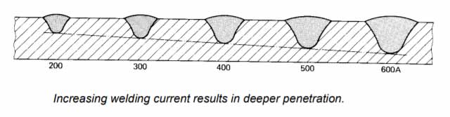
Higher the current, the deeper is the penetration. Multiple pass weld needs the current should suit the size of the weld in each pass. The electrode size may be a parameter for the selection of the amount of current for a weld.
Arc Voltage
The variation in arc voltage is within narrow limits. The bead width and shape get influenced as with higher arc voltage bead will be flat and wide.
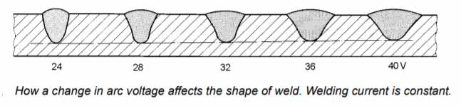
Extremely high arc voltage may cause cracking as the excessive melting of the flux with excess deoxidizers transferred to the welding zone to lower the ductility. More flux is consumed with high arc voltage. The low voltage generates a stiffer arc to improve penetration in the deep groove. The low voltage results in a narrow bead with high crown and difficulty in slag removal.
Travel Speed
Travel speed has an influence on the weld bead and penetration. The higher the speed, the thinner is the bead with less penetration. This is an ideal situation in sheet metal where a small bead with minimum penetration is needed. Too fast speed may produce undercuts and porosity because of faster freezing. Too slow speed creates bad beads, excessive spatter, and flash.
Secondary Variables
The angle of the electrode, angle of the work, the thickness of the flux layer, and the distance between the current tip and arc (Stickout). The normal distance between tip and arc is 25-38 mm.
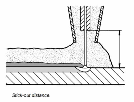
Increasing the stick-out will increase the deposition rate. We should consider this factor in detail for better results.
Wire stick-out should be about 8 times the wire diameter.
Depth of Flux
The thin layer of flux will produce more arcing and arc flash causing porosity. The heavy flux will cause a narrow and humped welding bead. Small impurities in flux produce pec marks on the bead.
Tips for the SAW Welding Process
The situation of circular weld when parts are rotated beneath the fixed head. The welding need may be inside or outside diameter. A large molten pool with slag moves to run in the SAW welding process. Weld deposition in outer diameter and the electrode should position at the top at 12 o’clock position. The weld metal moves down with solidification. The smaller diameter may be an issue in welding. The improper positioning of the electrode may cause slag inclusion and poor welding. A welding process, the inside circumference may need electrodes angled at 6o clock position.
Welding downhill and uphill produce different weld contours. In downslope the bead will have less penetration and wider. The uphill produces deep penetration with a narrow bead.
One side welding in the complete root penetration is possible with SAW welding. When joint with a tight root and large face the high current with a positive electrode is used. The minimum face with a wide root requires a backing bar as nothing is there to support a molten metal.
Copper backing bars are useful equipment when welding thin steel. The bars hold the molten material until it solidifies. The backing bars may have a water cooling facility to cool the metal faster.
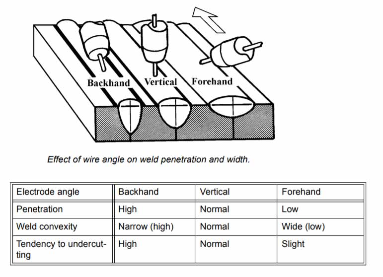
Wire Angle
Variations of the SAW Welding Process
- There are numerous variations to the process which add the extra capabilities to the submerged arc welding process. Few of the common variations are:
- Same power source with two-wire systems
- Separate power source with two-wire systems
- Separate power source with a three-wire system
- Surfacing strip electrode
- Iron additions to flux
- Long stickout
- Cold filler wire electrical
The Multi-Wire System – The multi-wire system improves deposition rates by using more electrodes. With a single power source, same drive roll used for both the electrodes. When two power sources are used individual wire feeders are used to insulation between two electrodes into the weld. With two power sources and two electrodes. It is possible to use different polarities and place both the electrodes, side by side. We call this a transverse electrode position. We can place one electrode in front of others in the tandem electrode position.
Two-Wire Tandem system – This position of electrode is required if the required penetration is extreme. The leading electrode here is positive while the trailing electrode is negative. The first electrode performs digging action while the second electrode fills the joint. In case two dc arcs are placed closely, the tendency of arc interference is there.
Strip welding system – It is used for mild steel and alloy steel with a wide bead with minimum and uniform penetration. We use it for overlaying the inside of vessels to provide the corrosion resistance of stainless steel. It uses a strip wire feeder with a special flux.
Iron Base under Flux – We can increase the deposition by adding an iron base material to joint under the blanket of flux. The iron will Mel here and become the part of a metal weld. The metal deposition increases without decreasing base material properties.
Cold filler wire – The electrically cold filler rod can be added as a special alloy to augment the deposition of the metal. It improves the properties of the deposited material. It is possible to use a flux-cored electrode here.
The Material used in SAW Welding
The welding flux and consumable electrode wire are the materials used in SAW welding. The flux layer shields both the arc and molten metal from atmospheric impurities of oxygen and nitrogen. It has properties of scavenger and deoxidizers which removes these impurities from the weld pool. The flux gives a property of alloy but once cooled it forms a glassy slag. The slag protects the surface of the welding. The unmelted flux remains unchanged and collects to reuse it for further operation.
The flux on melting forms a slag that can easily peel with little effort. The slag in the groove weld may need a chipping hammer to remove the slag. They design the fluxes for some specific uses. These fluxes come in sizes and particles are designed for a specific application.
Conclusion
It uses the submerged arc welding process for heavy metal and heavy structural welding. The fastest and strongest arc welding process available with the best deposition rates. The SAW welding is the process of welding chosen according to the need of the project. Whenever you need to weld in heavy welding in fabrication, pipe, boiler, and rail the submerged arc welding machine is your choice.
Now it is your turn to ask me a question. We are available for any help in making your choice.
Frequently Asked Questions
What is the saw welding process used for?
The industries where long wedding in the thick steels are required.The process involves making a joint between steel components using the electric arc submerged under a blanket of flux.
Why is submerged arc welding termed as submerged?
The process shows how the arc and welding zone is covered under the layer of flux. It is submerged under the flux.It becomes electrically conductive when heated and helps in arc creation.
Which type of electrode is consumed in saw welding?
In submerged arc welding two materials are used. The welding flux and consumable electrode wire. The flux provides a shield to the arc and molten metal from the impurities like oxygen and nitrogen.
What are the limitations with saw welding?
The few major limitations are, it can be performed in one flat welding position. The Molten metal makes it fit for 1F, 1G, and 2F position only. It is also unfit for the thin metals.
What type of electrode is consumed in submerged arc welding?
Both direct-current positive (DCEP) and direct current negative (DCEN) are used. The constant type of direct power is more popular for SAW welding with 3.2 mm and small wires.