
Weld Testing Methods: Destructive & Non-Destructive
The weld test methods listed below are greatly specialized, requiring skill and aptitude. These tests check the skill of the welding mechanic along with the quality of the weld metal and the strength of the welded joint for each variety of the metal used in industries.
Why do we need a welding test?
An error in the welding process may damage weld metals significantly resulting in the loss of strength, durability, and failure of the structure. These welding testing methods like visuals inspection and others are an assurance that products are secure for the intended use.
They ensure to meet the set standards for smooth sailing without many errors and possible extra expenses.
Physical Weld Testing Methods
These types of welding tests can broadly be divided into two types.
✓ Destructive testing
✓ Non-destructive testing (NDT)
These tests may detect defects commonly not visible to the naked eye.
Destructive Tests
The tensile and bending tests are destructive as the test specimens are loaded until they give out, to gain the desired information.
These destructive tests fall into two categories
✓ Test based on the workshop
✓ Laboratory tests like chemical, corrosive, microscopic, and macroscopic glasses use.
Non Destructive Tests (NDT)
The aim of these tests is the examination of the weld without imparting any damage. These may include x-rays, hydrostatic tests, etc, and are also termed NDE or nondestructive examination and NDI or nondestructive inspection.
Nondestructive Testing (NDT) Types
Types of Destructive Testing Physical Weld
1. Acid Etch Test
This physical weld testing is employed to ascertain the soundness of the weld. The acid attacks the edge of the defects in base metal or weld metal and identifies the weld defects. In the condition of the defect, the boundary becomes accentuated between base and weld metals and can define the defect clearly which is otherwise not visible to the naked eye. This test is performed along the cross-section of the weld joint.
The acid solutions used here are hydrochloric acid, ammonium persulfate, nitric acid, or iodine, and potassium iodide for the etching of carbon and low alloy steel.
2. Guided Bend Test
These guided bend tests are used to determine the quality of the weld metal at the root and face of the welded joint. They also judge the fusion and degree of penetration to the base metal along with the efficiency of the weld. The testing of this type can be done in a jig. The required specimens for testing are machined from the already welded plates, the thickness of these specimens should be within the capacity of our jig for bending. The specimen for testing is placed upon the supports of the die which is the lower part of the jig. The hydraulic jack’s plunger forced the specimen into it and assured the shape of the die seen.
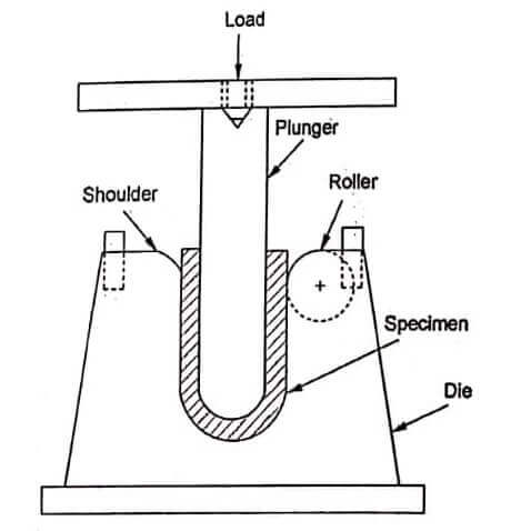
The requirement of this test is fulfilled by bending the specimens at 180 degrees and is now accepted as passable. No, a crack more than 3.2mm in any dimension should be visible on the surface. Face bend tests are made in the jig while facing the weld in tension means outside of the bend. Now the root bend test is made in the jig with the face of the weld in tension as on the outside of the bend. The guided bend tests are shown in the figure.
Notes:
✓ T-Test plate thickness
✓ A hardened roll may be utilized on shoulders if needed
✓ Specific dimension for 3/7 of the plate
✓ Every shown dimension is in inches.
3. Free Bend Test
This physical weld-free bend testing approach is designed to judge the ductility of the metal deposited in a weld joint. The specimen for this testing is procured by machining from the welded plate with the weld that came across as shown in A, figure.
Time to round each corner of the specimen lengthwise in a radius not exceeding 1/10 of the specimen’s thickness. Tool marks if any expected along the length of the specimen. Two scribed lines are put down on the face 1.6mm in from the edge of the weld. Now measure the distance between two lines in inches and record it as the initial distance X. The test specimen ends are bent through angles of approximately 30 degrees, these bends are about 1/3 of the length from each end. The weld point is located centrally to ascertain that all bending occurs in the weld.
The test sample bent, in the beginning, is placed in a machine that is capable of exerting a big compressive force and bent continually until a crack is more than 1/16 inches in any dimension seen on the face of the weld. In the condition of no crack, bending may be continued till the sample is 1/4 inches thick or under may be possible to test in a vise. The heavy plate is usually tested in bending jigs or a press.
You may use a power compression press or vise when doing the free bend test, it is better to machine the upper as well as the lower plate of the bending devices to present surfaces parallel to the ends of the test sample. This exercise will prevent the slipping and snapping of the specimen out of the testing equipment when it is bending.
Free bend test of the welded metal.
Once the bend test is concluded after bending the test specimen, the distance between the scribed lines is measured in inches and recorded as distance Y. To calculate the percentage of elongation, subtract the figure X from Y distance, divide it by Xor initial distance and multiply by 100. Usually, the requirement for passing this test is minimum elongation by 15% and no crack bigger than 1/16 inches in any dimension happens on the face of the weld.
This free bend test is substituted mainly by the guided bend test whenever we find the testing equipment at our disposal Backbend test.
4. Back Bend Test
This is a physical weld testing designed to ascertain the quality of the weld metal and the extent of penetration into the root of Y of the butt joint after welding. The sample or specimen used for testing is similar to the free bend test except they are bent with the root of the weld towards the tension side, or outside. The tested specimens need to bend 90 degrees without breaking away. This physical test is broadly replaced with a guided bend test.
5. Nick Break Test
This break test has been devised to detect in weld metal of the welded butt joint any internal defects like slag inclusions, poor fusion, gas pockets, oxidized metal, and burnt metal. Procure the sample from the welded joint by either machining or cutting by oxy-acetylene torch. Every edge of the joint is given a slot by a saw cut through the center. The prepared piece of the specimen is bridged across the two steel blocks. Now stuck the sample with a heavy hammer until the section of the weld between slots gets fractured.
The metal which is exposed needs to be completely fused and free from slag inclusions. Gas pockets if any should never be more than 1.6mm across the higher dimension, The number of gas pockets should not exceed 6.
To judge the soundness of the fillet welds another break test method is employed which is called as Fillet Weld Break Test. Here the force is applied with the press, hammer blow, and testing machine pressure applied to the apex of the V-shaped specimen until the fillet weld breaks away. Now examine the surface of the fracture for the soundness of the welding.
6. Tensile Strength Test
The tensile strength test is designed to test the strength of the welded joint. A segment of the, to be tested, the welded plate is placed the weld midway in the jaws of the testing machine. The width and thickness of the test sample are measured before the testing. To calculate the area in square inches multiply this before testing, and calculated by multiplying these 2 figures as in the formula of Figure.
The specimen for the tensile physical weld strength test is now mounted on a machine that will exert enough pulling force to break the sample. The machine for testing may be portable or stationary type. A portable testing machine working on a hydraulic principle that is enough to pull and bend the specimen is shown in Figure.
While testing is being performed on this machine the load in the pound is visible on the gauge. The stationary-type machine shows the load applied on the balancing beam. In every case, the load is recorded at the point of breaking. The specimens broken by the tensile strength test are shown in Figure.
Tensile strength and bend testing portable machine.
The tensile strength has defined stress in pounds per square inch. It is calculated once dividing the break load of the specimen by the initial cross-sectional area of the test piece. The acceptable norms for the tensile strength of the welds are that the specimen shall pull not less than 90% of the base metal tensile strength.
The shearing strength of longitudinal and transverse fillet welds is assessed by the tensile stress of the test samples. The width of the test sample is measured in inches. The test sample is ruptured under the tensile load, and the maximum load in pounds is marked. The shearing strength is determined by dividing the maximum load by the length of the fillet weld that had ruptured. It is marked as a pound per linear inch. The shearing strength in pounds/inch can be obtained by dividing the shear strength in pounds / linear inch by the average throat dimension of the weld in inches. The specimens are made wider than the requirement and machined to the required size.
Non Destructive Tests
1. Hydrostatic Test
This type of physical testing by the non-destructive test is performed to check the welding quality in a closed container such as tanks and pressure vessels. The testing is performed by filling the vessel with water and exerting a pressure more than the working pressure of the vessel. Large tanks are filled with water sometimes, without any pressure to ascertain the possible leakage due to defective welds. Sometimes we can do the testing for leakage with the help of oil where steam went out of the vessel and get visible as seepage of oil.
2. Magnetic Particle Test
This inspection method or physical weld testing method is employed on welds and articles made of magnetic alloy steels. This test is used only for ferromagnetic materials where deposited material is also ferromagnetic. A robust magnetic field is created in the test piece by means of high-amperage electric currents.
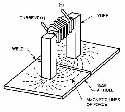
The field where the leakage is felt is set up by any breach that intercepts the fields in the testing part. The poles are locally produced by the occurrence of leakage fields. The generated poles attract and keep the hold on magnetic particles placed on the surface for the designated purpose. The defect or discontinuity pattern, shown by these particles over the surface of the part is an indicator of the defect.
3. X-Ray Testing
This physical weld testing radiographic method reveals the presence and nature of the internal defects in a sample of the weld, like cracks, blowholes, slag, and improper fusion zones. We keep an x-ray tube on one side of the sample welded plate and an x-ray film specially designed sensitive emulsion on the other side. In the case of the developed defects in the metal plate, it shows up as dark spots and bands. These defects can be interpreted by an operator experienced in these inspection methods.
The x-ray inspection here is showing porosity and deep root penetration as shown in Figure.
4. Gamma-Ray Test
This radiographic physical weld testing & inspection method is similar to an x-ray method except that these gamma rays emerge from a capsule of radium sulfate instead of a tube in the x-ray.
The feature of the short wavelength of gamma rays finds it perfect for penetrations of larger thickness sections. The time required for exposure is longer than the x-ray because of a slower rate of gamma rays production.
X-ray testing is most often used in radiographic inspections, but portability is the unique feature of the gamma rays.
5. Fluorescent Penetrant Dye Test
This fluorescent penetration physical weld non-destructive test is designed to locate the leaks, cracks, pores, and discontinuity in the materials. It is a choice of test for non-magnetic materials like magnesium, aluminum, and austenitic steel to locate any leak in every type of weld. The dye is water washable and highly fluorescent with exceptional penetration qualities.
The dye is applied over the surface to be tested by brushing, spraying, and dipping. The excess material is removed by wiping and rinsing, with a water-soaked cloth. The developer may be dry or wet applied over the surface after properly cleaning it. The penetrant treated with the developer shows brilliant fluorescent indicators under black light.
Advantages of the Dye Test Method
✓ Economical with a low cost
✓ Easy process and its interpretation
✓ Not much training required
✓ Used for ferrous and nonferrous metals
Disadvantages of this Physical Method
✓ May skip the problem under the surface
✓ Does not work on a porous surface
Types of Dye
Type A – This type of dye emits visible light once viewed using a black light.
Type B – The bright color dye can be examined by a regular light and used easily in the field.
6. Hardness Test
The ability of the substance to thwart the indentation of localized shift is defined as hardness. We can simply say resistance to wear, abrasion, and indentation. This non-destructive test is commonly used in laboratories, but not usually in the field. The test of hardness is used as a means of controlling the properties of the materials as the particular hardness is achieved for that particular application.
The test is used to determine the hardness of the weld metal. Examine the weld joint carefully to locate the hard area and decide the effect of welding heat on the baseline properties of the base metal drawn.
Hardness Test Equipment
File Test
The file test determines the comparative hardness in a very simple method. We run a file under manual pressure over the sample to be tested. We can record information on whether the metal tested is harder or softer than the file and whether other metals have been delineated with the same treatment.
Hardness Testing Pieces of Equipment
There is a big range of hardness testing machines and each of the machines is designed for that particular function in a given situation. Moreover, machines of more than one type can be designed for a given metal and obtained hardness can be correlated satisfactorily. Two common types of machines used for metal hardness are:
✓ The Brinell hardness tester.
✓ The Rockwell hardness tester
Brinell Hardness Tester
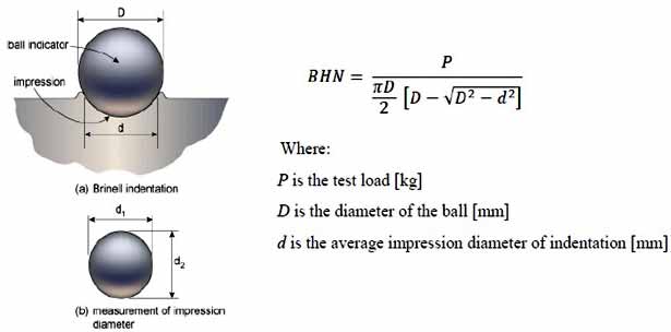
In this procedure, the sample remains minted on the anvil of the machine and applies a load of 6620 pounds (3003 kg) is against a hard steel ball that remained in contact with the surface of the sample to be tested. The steel ball is 10.2 mm in diameter and the load is meant to remain in contact for 1/2 minute. Now release the pressure and measure the depth of the depression made by the ball on the sample and note the depth. The diameter of the depression is more important than the depression to calculate the hardness by Brinell hardness. The charts of Brinell hardness numbers can be prepared for a range of diameters of various impressions, These charts are employed to determine Brinell numbers.
The Brinnell hardness number is calculated by the following formula.
Here are the details
HB – Brinell hardness number
D – Ball diameter in mm
d – Diameter of the recovered indentation in mm
P – Load applied in kg
Rockwell Hardness Tester
The principle of testing here is the same as that of the Brinell tester. The difference from the Brinell tester is that here less load is needed to impress on a smaller ball /cone-shaped diamond. The indentation depth can be measured with a dial attached to the machine. The hardness here is expressed arbitrarily as Rockwell numbers. These numbers are prefixed with a letter such as “B” or “C” to demonstrate the size of the ball used, the load for impression, and the scale used in the specific test.
Others tests available are the Vicker diamond pyramid and stereoscope.
7. Magnaflux Physical Weld Test
This is a rapid non-destructive physical weld test to localize the defect at or near the surface of the steel metal and magnetic alloys by employing means of correct magnetization with ferromagnetic particle application.
Basic Principle of Magnaflux Test
In general, saying the magnaflux inspection may be likely to use a magnifying glass as a physical weld test method. Here instead of using glass, the magnetic field and ferromagnetic material are employed. The method is based on two principles:
✓ A magnetic field is produced when an electric current has flowed through a metal.
✓ The minute poles are formed on the surface where the magnetic fields are broken or distorted.
When this ferromagnetic stuff is brought into the vicinity of the magnetized part, they by nature attract strongly towards these poles and hold there firmly and form a visible indication.
8. Electromagnetic Eddy Current Testing
Magnetic particle testing for surface defects of ferrous metals.
This electromagnetic nondestructive test is based on the principle that an electric current always flows in a conductor subject to changing magnetic fields. This test is useful to check welds in nonmagnetic and magnetic materials and is a very useful tool in testing fillets, bars, tubes, and welded pipes. The frequency may vary from 50Hz to 1MHz according to the type, and thickness of material current methods. The former happens to test when the permeability of the material is a deciding factor and the latter where electrical conductivity is the element of consideration.
The testing here involves the induction of the electric current like Eddy or Foucault currents in the test piece and recording the changes that happened in those currents or any physical differences in the test metal piece. These tests can not only detect discontinuity in test metal pieces but can measure the dimensions and resistivity. The resistivity is proportional to the chemical properties, heat treatment, crystal orientation, and hardness and these can be judged indirectly. These electromagnetic test methods are classified as magneto-inductive & Eddy current methods.
The method to produce the Eddy current in a test specimen is to make the test specimen the core of an alternating current induction coil. The two ways can measure changes that occur in the magnitude and dispersal of these currents. The first is to measure the resistive component of the impedance of the secondary coil and the second is to measure the inductive component of the impedance of the secondary coil. The types of equipment have been designed to measure either resistive or inductive impedance components individually or simultaneously for both.
The Eddy current can be induced in the testing specimen by alternating electromagnetic transformer action. This current is electrical in nature with all its properties. To generate Eddy current, the test sample piece must be an electrical conductor brought into the fields of a coil carrying alternating current. The coil may encircle the sample in the form of a probe and in case of tubular shape, wound to fit inside the pipe or tube. This current in the metal test piece may set up its own magnetic fields to oppose the original magnetic fields. The impedance of the secondary coil coupled to the first in close proximity to the test sample is forced by the presence of the eddy current to change. The second coulis is often used as a convenience, sensing, or pick-up coil. The path of this eddy current may show distortion in case of any discontinuity. The eddy current may divert or crowd in the case of discontinuity or defects. The change can be measured and it is an indication of defects/ differences in chemical, physical, and metallurgical structure.
9. Acoustic Emission Testing
The acoustic method is to strike the weld and determines the quality by the tone.
This physical weld test acts as a supplement to other nondestructive tests. They have applied this testing during the proof, recurrent testing, service, and fabrication work. This test comprises the detection of acoustic signals generated as a result of plastic deformation or any crack formation while loading. These signals are wide spectrum with ambient noise from many other sources. The transducer, if strategically placed on the structure, is activated by incoming signals. Ambient sound can be reduced considerably by adding filters. The source of significant signals is marked based on arrival time at different transducers.
10. Ferrite Testing
Effects of Ferrite Content
The austenitic stainless steel weld deposits have the natural to develop small fissures even under circumstances of minimal restraint. These fissures are seen generally transverse to the weld fusion line in the weld passes on reheating to near the melting point. These cracks are injurious defects and are difficult to tolerate. The effects of these fissures on weld performance are less clear as these micro-fissures are quickly covered by a tough austenitic matrix. These fissured weld metals performed satisfactorily under very severe conditions. A tendency to form large fissures goes hand in hand with larger crack formations. It is always desirable to avoid fissure-sensitive weld metals.
A small fraction of magnetic delta ferrite phase in nonmagnetic weld deposits leads to the prevention of both cracking and fissuring at the centerline. The excessive delta ferrite, however, can have adverse effects on weld metal properties. The more the delta ferrite, the less will be ductility and toughness. More exposure to severe temperatures makes the metal brittle. and hampers the quality.
Portable indicators of ferrite are designed for onsite use. Ferrite content in weld deposits is indicated in percent ferrite and may be bracketed between 2 values. This will offer sufficient control in applications where the minimum ferrite content/ ferrite range is specified.
Related Articles
Introduction to Nondestructive Testing
Non-Destructive Testing of Welds
You May Also Like:
Quality Weld Inspection – Nondestructive Testing
12 Different Types Of Welding Processes [The Definitive Guide]
Dear Ramakant Sharma , we really appreciate your effort for publishing this article for the welding test. It was very detailed and impressive to learn . Wish you best of luck for your future endeavors.